Ever stared at a pump and thought, “All that spinning and moving and I still have no idea what’s actually going on in there?” You’re not alone. Centrifugal pumps are among the most common pieces of equipment in industrial settings. You’ll find them in chemical plants, power generation systems, food and beverage facilities, and water treatment plants, where they quietly move fluids where they need to go.
Understanding how these workhorses operate can help you next time you’re troubleshooting performance issues or evaluating specs for a new system.
That’s why we’re breaking things down in this blog, minus the jargon overload.
Here's what you’ll find:
-
A simple explanation of what centrifugal pumps are built to do
-
Key components and how they create pressure, velocity, and flow
-
Real-world applications where they perform best
-
Common limitations and when to consider other pump types
Let’s start by spinning up the basics: what exactly is a centrifugal pump designed to do?
The Purpose of a Centrifugal Pump
At its core, the centrifugal pump is a mover. Its Job? To transfer fluids using rotational energy, typically from a motor, to generate flow and pressure.
Here’s how it works: when the pump is running, an impeller spins inside a casing. This spinning motion slings the fluid outward (think: spinning a wet paintbrush), converting mechanical energy into kinetic energy. That energy is then transformed into pressure, pushing the fluid through your system.
Centrifugal pumps are especially useful when:
-
You need to move large volumes of fluid quickly
-
You’re dealing with low-viscosity liquids like water, chemicals, or fuels
-
Your system has a consistent flow requirement without dramatic fluctuations
Whether you're filling tanks, circulating cooling water, or transferring chemicals, centrifugal pumps are designed to keep things moving when used in the right process.
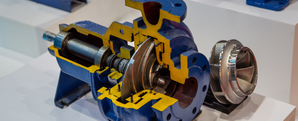
Inside the Pump: How Components Create Flow and Pressure
Centrifugal pumps convert mechanical energy into fluid movement using a precise combination of velocity and pressure. To understand how they work, it helps to look at both the physical components inside the pump and the fluid dynamics they generate.
Let’s start with the key parts:
Core Components
-
Impeller: A rotating disc with vanes that add velocity to the fluid.
-
Pump Casing: Encloses the impeller and directs flow from suction to discharge.
-
Inlet (Suction) Port & Discharge Port: Where fluid enters and exits the pump.
-
Volute (or Diffuser): Expands to convert fluid velocity into pressure.
-
Motor Shaft & Seal: Transfers energy to the impeller while containing pressure.
Now, here’s how those parts interact to move fluid:
Creating a Low-Pressure Zone
When the impeller spins (typically between 1,000–3,600 RPM), its blades fling fluid outward, creating a drop in pressure at the impeller’s center (the "eye"). This low-pressure zone draws fluid into the pump from the source due to atmospheric or system pressure.
This is why priming is essential for non-self-priming pumps—without liquid, the impeller can’t generate suction.
Fluid Acceleration
As fluid enters the impeller’s eye, the spinning blades accelerate it outward. The curved vanes increase both radial and tangential velocity, raising the fluid’s kinetic energy.
-
Impeller design matters: Closed impellers are efficient with clean fluids; semi-open or open styles are better for solids or slurries.
Energy Conversion in the Casing
High-velocity fluid leaves the impeller and enters the casing’s volute or diffuser. As the flow area expands, velocity decreases and pressure increases (per Bernoulli’s principle).
The volute’s spiral shape helps maintain smooth, efficient flow toward the discharge port while minimizing turbulence and energy loss.
Discharge and Continuous Operation
The pressurized fluid exits the discharge port, moving through piping systems and overcoming resistance (e.g., elevation or friction).
Meanwhile, the low-pressure zone at the impeller’s eye continuously pulls in new fluid, keeping the cycle in motion as long as the pump is running and the system remains primed.
When you see how each part contributes to the movement and pressurization of fluid, it’s easier to understand the full picture. Let’s take a visual look at how these components fit together inside a centrifugal pump.
Centrifugal Pump Diagram
It’s easier to understand the magic when you can see it. Below is a simple centrifugal pump diagram highlighting its core components and how they work together.
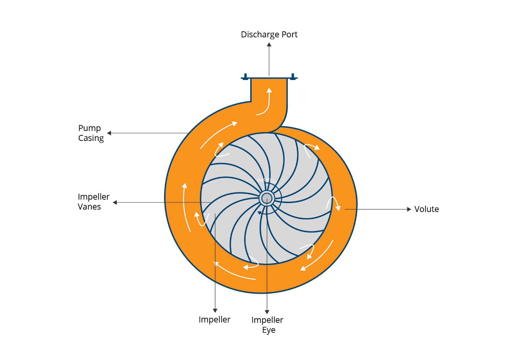
Diagram Key Components:
-
Impeller – The spinning part that moves the fluid
-
Volute (or Diffuser) – Converts velocity into pressure
-
Pump Casing – Holds everything together and directs flow
-
Suction & Discharge Ports – Entry and exit points for fluid
-
Motor Shaft – Transfers energy to the impeller
Understanding this layout can help you diagnose issues, choose the right pump, and improve long-term system performance.
Common Applications for Centrifugal Pumps
|
Types of Centrifugal Pumps |
Applications |
Features |
|
End-Suction |
|
|
|
Self-Priming Centrifugal Pump or Submersible Centrifugal Pump |
|
|
|
Magnetic Drive |
|
|
|
Inline Centrifugal |
HVAC |
|
Could one of these apply to your facility?
Let’s talk about where centrifugal pumps could improve your process.
Limitations of Centrifugal Pumps
Centrifugal pumps are versatile, but they’re less effective for high-viscosity fluids or low-flow, high-pressure applications, where positive displacement pumps perform better. They also require sufficient inlet pressure to avoid cavitation and maintain reliable performance.
Here are a few common limitations to keep in mind:
Poor Performance with High-Viscosity Fluids
Centrifugal pumps rely on velocity to move liquid, which works well with thin fluids. But with thicker materials—like heavy oils, sludges, or syrups—the pump struggles to generate enough flow or pressure to move the fluids. In these cases, a positive displacement pump is often the better choice.
Not Ideal for Low Flow, High Pressure Needs
These pumps shine when moving large volumes at moderate pressure. But if your system needs precise flow control or has high-pressure requirements at low flow rates, like metering or dosing applications, you’ll likely need a different type of pump.
Ready to put this knowledge to work? Whether you’re selecting a new pump, troubleshooting performance, or comparing options, our team can help you find the right solution for your process.